


We made several measurements of the running code, which can be divided into three categories:\
Machine-independent Measurements
These are measurements of the quality of the solution to the graph-partitioning problem which are independent of the particular machine on which the code is run.
Let us define load imbalance to be the difference between the maximum and minimum numbers of elements per processor compared to the average number of elements per processor. More precisely, we should use equations (i.e., work) per processor as, for instance, with Dirichlet boundary conditions, the finite element boundary nodes are inactive and generate no equations [Chrisochoides:93a].
The two criteria for measuring communication overhead are the total traffic size, which is the sum over processors of the number of floating-point numbers sent to other processors per iteration of the Laplace solver, and the number of messages, which is the sum over processors of the number of messages used to accomplish this communication.
These results are shown in Figure 11.16. The load imbalance is significantly poorer for both the SA runs, because the method does not have the exact balance built in as do the RB methods, but instead exchanges load imbalance for reducing the communication part of the cost function. The imbalance for the RB methods comes about from splitting an odd number of elements, which of course cannot be exactly split in two.
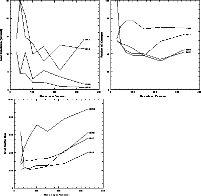
Figure 11.16: Machine-independent Measures of Load-Balancing Performance.
Left, percentage load imbalance; lower left, total amount of
communication; right, total number of messages.
There is a sudden reduction in total traffic size for the ORB method between the fourth and fifth stages of refinement. This is caused by the geometry of the mesh as shown at the top of Figure 11.15; at the fourth stage the first vertical bisection is just to the left of the light S-shaped region creating a large amount of unnecessary communication, and for the fifth and subsequent stages the cut fortuitously misses the highly refined part of the mesh.
Machine-dependent Measurements
These are measurements which depend on the particular hardware and
message-passing software on which the code is run. The primary
measurement is, of course, the time it takes the code to run to
completion; this is the sum of startup time, load-balancing time,
and the product of the number of iterations of the inner loop times the
time per iteration. For quasi-static load balancing, we are assuming
that the time spent on the basic problem computation is much longer
than the load-balance time, so parallel computation time is our primary
measurement of load-balancing performance. Rather than use an
arbitrary time unit such as seconds for this measurement, we have
counted this time per iteration as an equivalent number of floating-point
operations (flops). For the nCUBE, this time unit is  for a 64-bit multiply. Thus, we measure flops per iteration
of the Jacobi solver.
for a 64-bit multiply. Thus, we measure flops per iteration
of the Jacobi solver.
The secondary measurement is the communication time per iteration, also measured in flops. This is just the local communication in the graph, and does not include the time for the global combine which is necessary to decide if the Laplace solver has reached convergence .
Figure 11.17 shows the timings measured from running the test sequence on the 16-processor nCUBE. For the largest mesh, the difference in running time is about 18% between the cheapest load-balancing method (ORB) and the most expensive (SA2). The ORB method spends up to twice as much time communicating as the others, which is not surprising, since ORB pays little attention to the structure of the graph it is splitting, concentrating only on getting exactly half of the elements on each side of an arbitrary line.
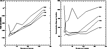
Figure 11.17: Machine-dependent Measures of Load-Balancing Performance.
Left, running time per Jacobi iteration in units of the time for a
floating-point operation (flop); right, time spent doing local
communication in flops.
The curves on the right of Figure 11.17 show the time spent in local communication at each stage of the test run. It is encouraging to note the similarity with the lower left panel of Figure 11.16, showing that the time spent communicating is roughly proportional to the total traffic size, confirming this assumption made in Section 11.1.2.
Measurements for Dynamic Load Balancing
After refinement of the mesh, one of the load-balancing algorithms is run and decisions are reached as to which of a processor's elements are to be sent away, and to which processor they are to be sent. As discussed in Section 10.1, a significant fraction of the time taken by the load balancer is taken in this migration of elements, since not only must the element and its data be communicated, but space must be allocated in the new processor and other processors must be informed of the new address of the element, and so on. Thus, an important measure of the performance of an algorithm for dynamic (in contrast to quasi-dynamic) load balancing is the number of elements migrated, as a proportion of the total number of elements.
Figure 11.18 shows the percentage of the elements which migrated
at each stage of the test run. The one which does best here is ORB, because
refinement causes only slight movement of the vertical and horizontal median
lines. The SA runs are different because of the different starting
temperatures: SA1 started at a temperature low enough that the edges of the
domains were just ``warmed up,'' in contrast to SA2 which started at a
temperature high enough to completely forget the initial configuration and,
thus, essentially all the elements are moved. The ERB method causes the
largest amount of element migration, which is because of two reasons. The
first is because some elements are migrated several times because the load
balancing is done in  stages for P processors; this is not a
fundamental problem, and arises from the particular implementation of the
method used here. The second reason is that a small change in mesh
refinement may lead to a large change in the second eigenvector; perhaps
a modification of the method could use the distribution of the mesh before
refinement to create an inertial term so that the change in eigenvector as
the mesh is refined could be controlled.
stages for P processors; this is not a
fundamental problem, and arises from the particular implementation of the
method used here. The second reason is that a small change in mesh
refinement may lead to a large change in the second eigenvector; perhaps
a modification of the method could use the distribution of the mesh before
refinement to create an inertial term so that the change in eigenvector as
the mesh is refined could be controlled.
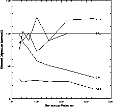
Figure 11.18: Percentage of Elements Migrated During Each Load-Balancing
Stage. The percentage may be greater than 100 because the recursive
bisection methods may cause the same element to be migrated several
times.
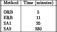
The migration time is only part of the time taken to do the load balancing, the other part being that taken to make the decisions about which element goes where. The total times for load balancing during the seven stages of the test run (solving the coloring problem plus the migration time) are shown in the table below:\
For the test run, the time per iteration was measured in fractions of a second, and it took few iterations to obtain full convergence of the Laplace equation, so that a high-quality load balance is obviously irrelevant for this simple case. The point is that the more sophisticated the algorithm for which the mesh is being used, the greater the time taken in using the distributed mesh compared to the time taken for the load balance. For a sufficiently complex application-for example, unsteady reactive flow simulation-the calculations associated with each element of the mesh may be enough that a few minutes spent load balancing is completely negligible, so that the quasi-dynamic assumption is justified.