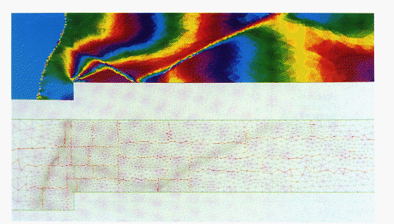
Figure 12.8: Pressure and mesh for a Mach 3 wind tunnel with a step. The red lines in the mesh separate processor domains. The mesh has been dynamically adapted and load-balanced with orthogonal recursive bisection.


Figures 10.8 and 10.9 (Color Plates) show the pressure and computational mesh resulting from Mach 0.8 flow over a NACA0012 airfoil at 1.25 degrees angle of attack, computed with a 32-processor nCUBE machine. This problem is that used by the AGARD working group [AGARD:83a] in their benchmarking of compressible flow algorithms. The mesh has 5135 elements after four stages of adaptive refinement. Each processor has about the same number of elements. In the pressure plot is also shown the sonic line; the plot agrees well with the AGARD data.
Note the shock about 2/3 of the way downstream from the leading edge, and the corresponding increase in mesh density there.
Figure 12.8 (Color Plate) shows pressure in a wind-tunnel with a step. A Mach 3 stream comes in from the left, with a detached bow-shock upstream from the step. A second shock is attached by a Mach stem to the bow shock, which is then reflected from the walls of the wind tunnel.

Figure 12.8: Pressure and mesh for a Mach 3 wind
tunnel with a step. The red lines in the mesh separate processor domains.
The mesh has been dynamically adapted and load-balanced with orthogonal
recursive bisection.
Notice how the mesh density is much greater in the neighborhood of the shocks and at the step where the pressure gradient is high. This computation was performed on 32 processors of a Symult machine.